MEG Drift Chamber
This page is under construction. Contents are updated occasionally.
DC construction

  • Up-to-date Status : see current status in this page (18/11/2007 updated !!)
  • Overview

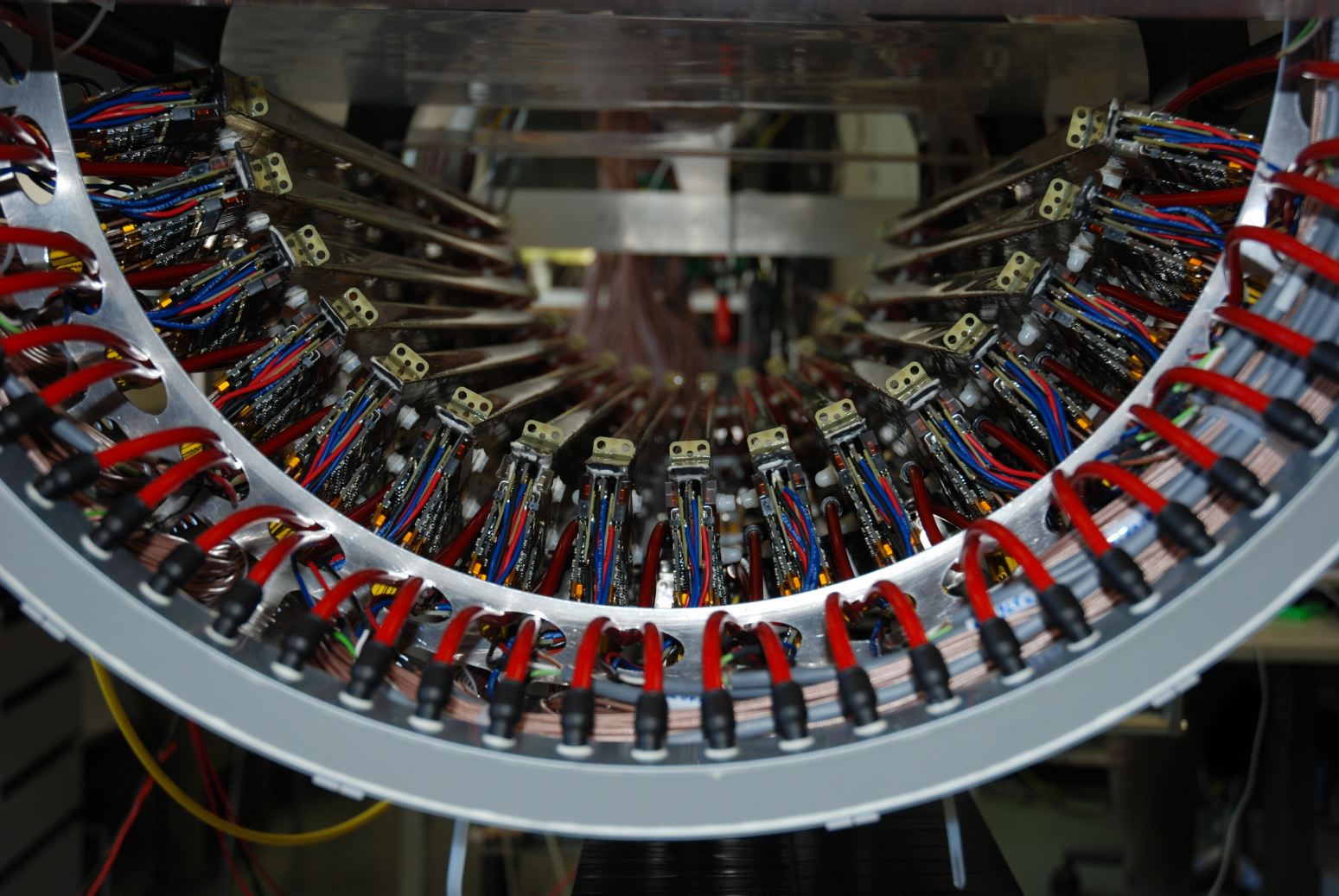
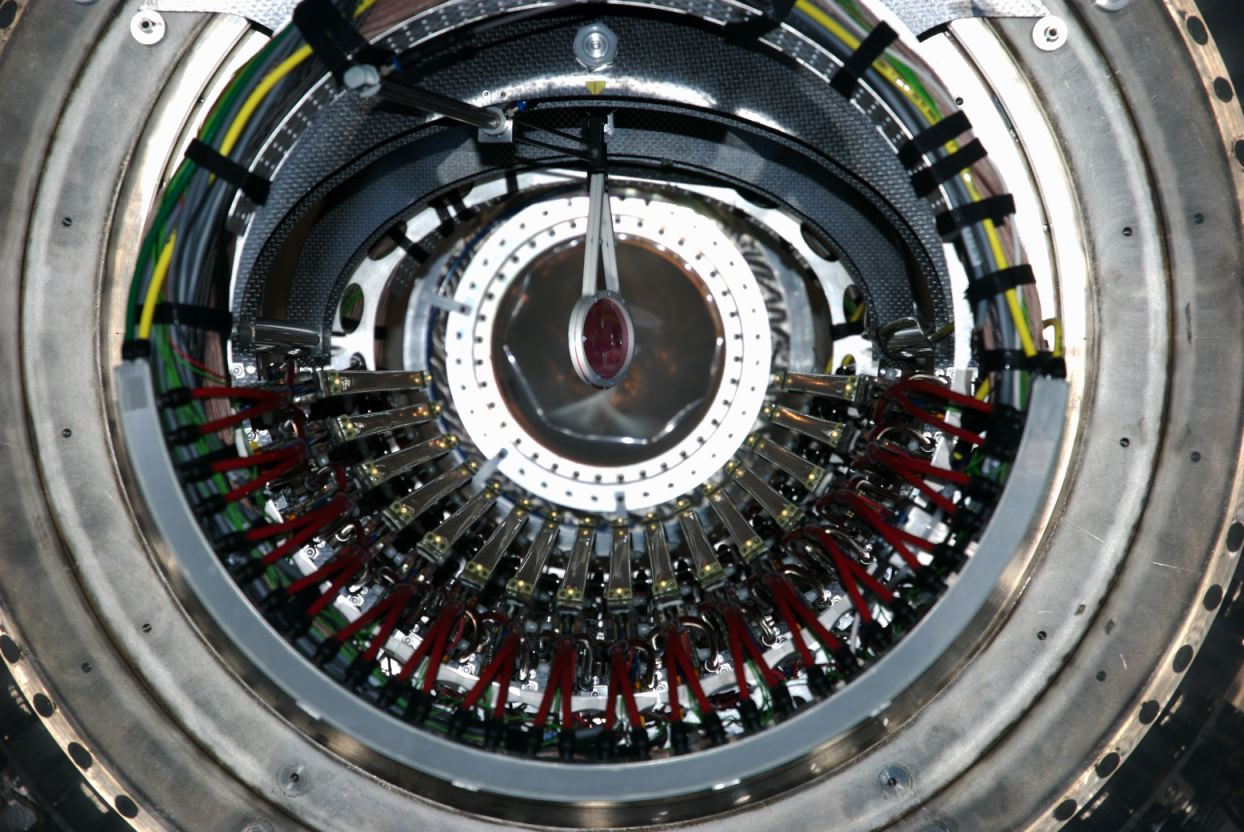
    The MEG positron spectrometer consists 16 drift chambers as shown in Fig 1. (only 6 sectors are shown to simplify view). These are aligned radially at 10.5 ° intervals in azimuthal angle. For the each DC module, two layers of axial sense wires and potential wires stretched by a 4.5 mm pitch are formed on the carbon-fibre frame. Each layer is isolated by a ultra-thin cathode foil, described later, and shifted by one-half cell to allow a local resolution of left-right ambiguity. 
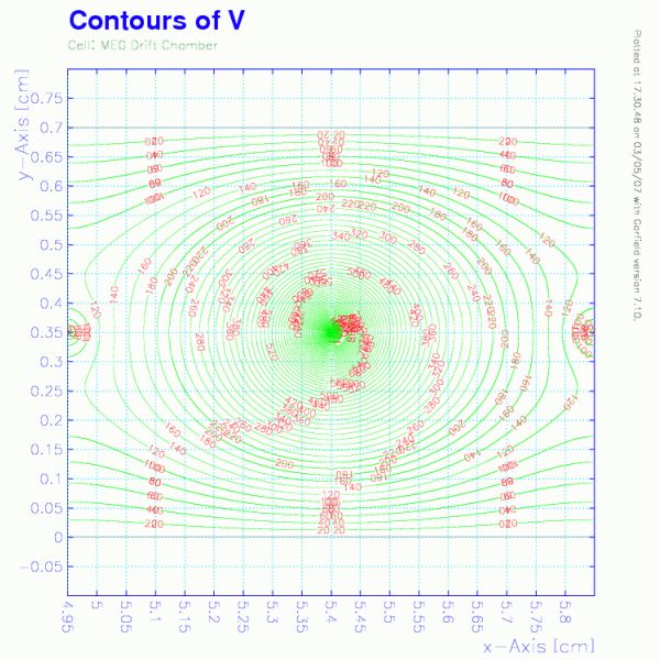
A schematic cross-sectional view of a part of single chamber module is shown in Fig 2.

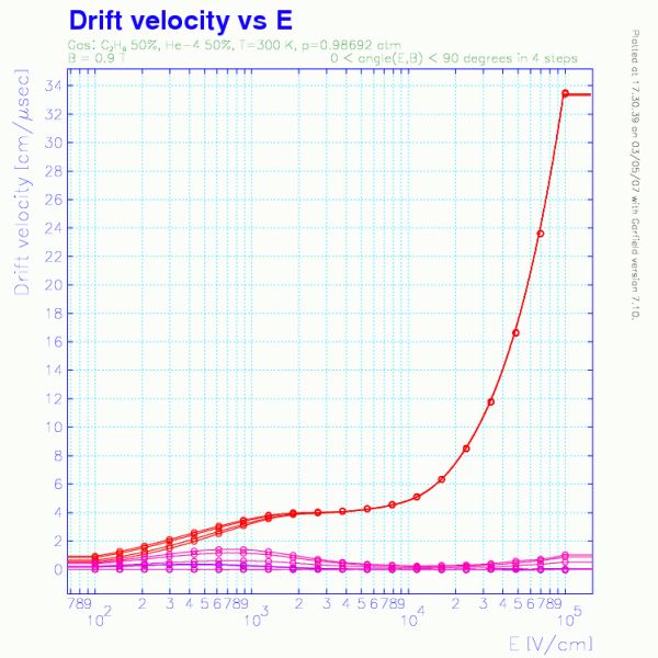
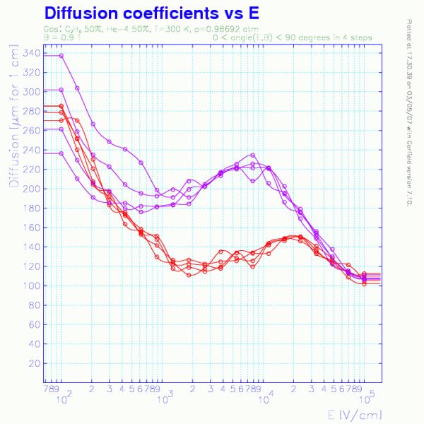
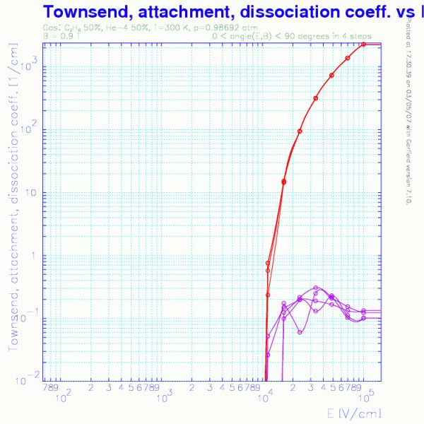
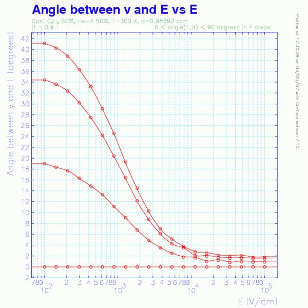
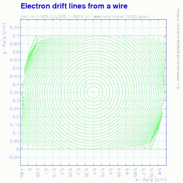
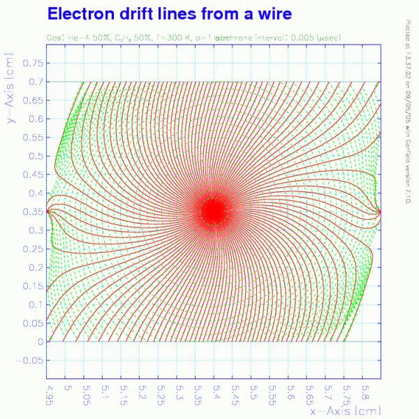
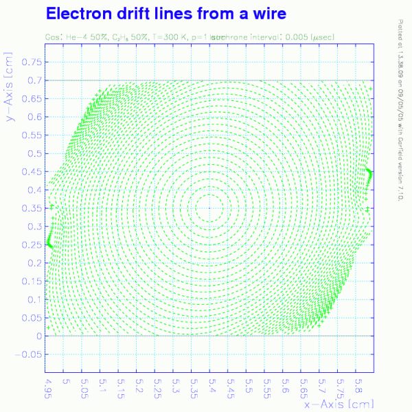
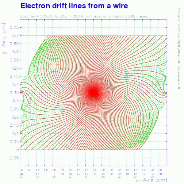
    In order to reduce the amount of material used in the spectrometer, a helium based gas mixture (50% helium and 50% ethane at 1 atm) is adopted as a chamber gas. Additionally, the gaps between each chamber module are filled with pure helium gas. The chamber wall is made of an extremely thin foil, 12.5 μm thick polyimide with aluminum deposition (2500 Å). 
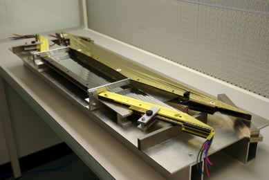
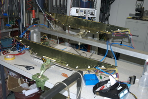
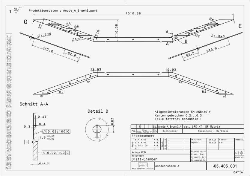
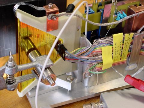
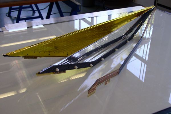
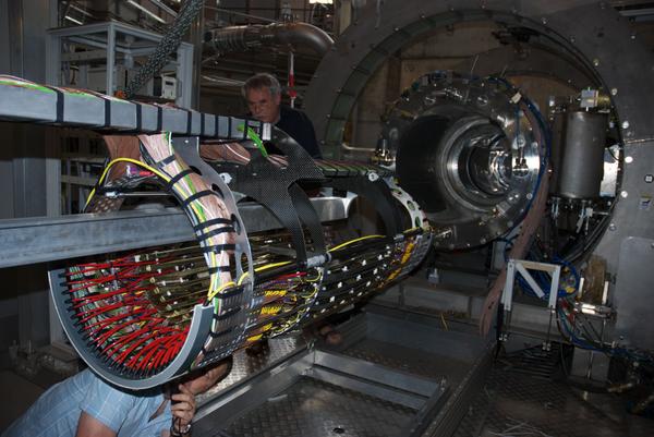
The frame of drfit chamber is shaped without any structure on the muon stopping target side. This opend-frame (see photo, Fig 3.) makes wire/foil-stretching more challenging but helps very much. Thanks to such an exhaustive reduction of material, the overall material in the fiducial tracking volume amounts to 0.002 X0 on an average for the signal positron (52.8MeV/c) trajectry.

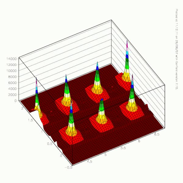
    The staggered-cell configuration allows us to measure the r-coodinate and the absolute time of the track simultaneously. Difference between the drift times (t1-t2) in the adjacent cells gives the r-coodinate of the track with 200 μm accuracy, while the mean time (t1+t2)/2 gives the absolute time of the track with 5 nsec accuracy. 
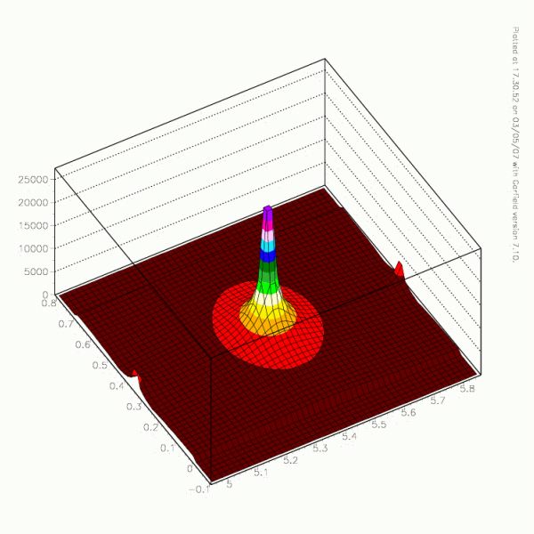
On the other hand, the ratio of charges collected at both ends of a sense wire gives the z-coordinate (muon beam direction) roughly with an accuracy of approximately 1cm. Moreover, ultra-thin aluminum deposit on the cathode foil is patterned to make a 5cm period Zig-Zag strip, called "vernier pad" (Fig 4.). The amount of induced positive charge on each vernier pad is related to the z-coordinate because of this Zig-Zag shape. Concequently, the ratio of charges induced on each pad gives the z-coordinate precisely to an accuracy of 300∼500 μm.


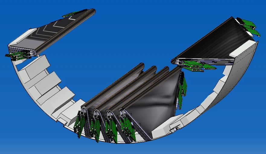
    Fig 1. MEG DC Overview


    Fig 2. Cell configuration


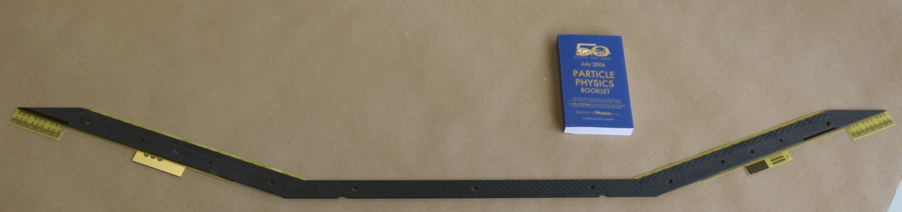
    Fig 3. Opened anode frame


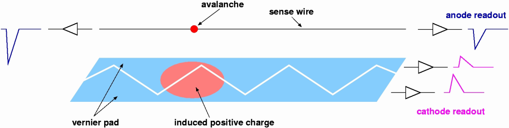
    Fig 4. Schematic view of the vernier pad method

  • Items
  • Drawings
    • Anode frame (side A) ( DXF, PDF )
    • Anode frame (side B) ( DXF, PDF )
    • Cathode foil pattern (vernier pad) ( DXF, PDF )
      • labeled version ( PDF)

  • Prototype Results
  • Garfield Simulation Results
    • Gas properties
    • drift velocity
      diffusion coefficient
      Townsend coefficient
      Lorentz angle

      * He:C2H6=50:50, T=300K, p=1atm, B=1.155T, with 4 kinds of incident angle (0 < θ(E,B) < 90° in 4 steps)

    • Calculated fields
    • - Overview:
      V (contour view)
      V (surface view)
      E (contour view)
      E (surface view)
      - Magnified-view:
      V (contour view)
      V (surface view)
      E (contour view)
      E (surface view)

      * "V" is presented as "-V" (inverted) in order to take a more detailed look at close to the sense wire.
      * "E" is displayed up to 10kV/cm. (The 1st Townsend coefficient becomes more than 1 at E ∼ 10kV/cm)

    • Drift properties
    • Isochrones (B=0.9T)
      Drift lines (B=0.9T)
      Isochrones (B=1.6T)
      Drift lines (B=1.6T)

      * Isochrone lines are shown at 5nsec intervals.

  • Softwares
  • Basically, all MEG Software information can be obtained by visiting the MEG Wiki page (restricted).
  • Gallery

    You can see a lot of pictures on the MEG DC at the MEG Gallery page.
    Here are the lists of main contents of the DC gallery.

  • DC Assembly/Construction
    • Cathode , pre-tension for inner cathode frame, foil preparation, cathode mounting, etc.
    • Hood , pre-tension for cathode hood, making/stretching Rohacell® bridge, hood mounting, etc.
    • Anode , pre-tension for anode frame, wire stretching, soldering, etc.
    • Assembly , final assembly, test, sealing, etc.

  • Installation
    • Mount , Mounting DC on support, Checks etc.
    • Transport , Transportation from Lab. to Experimental Hall
    • Installation , DC system install into the COBRA, and a Celebration
  • Events
    (as of 18/11/2007)
  • Production/Construction
    • Cathode ; completed
    • Hood ; completed
    • Anode ; completed
    • Assembly ; all completed !! (03/07/2007)
    • Spare module ; progressing

  • Test
    • Low voltage conditioning (before sealing) ; completed
    • Test with RI source in the test bench ; completed (13/07/2007)
    • Test with Cosmic-ray on the support ; completed (19/07/2007)
    • all test in Lab, completed !! (19/07/2007)

  • Installation (in Lab.)
    • Support structure ; ready
    • Chamber mounting ; completed !! (13/07/2007)
    • Cabling/Labeling ; completed
    • Gas tubing ; completed
    • Position measurement ; completed
    • installation in Lab, completed !! (20/07/2007)

  • Installation (in COBRA)
    • transport ; transported on 23/07/2007
    • install into COBRA ; completed (25/07/2007)
    • cosmic ray counter mounting ; completed (27/07/2007)
    • COBRA DS-EC closing ; closed (14/08/2007)
    • cabling ; completed (17/08/2007)

  • Operation and DAQ
    • gas flushing ; started (23/08/2007)
    • HV conditioning ; started (24/08/2007)
    • DAQ frontend ; launched (06/09/2007)
    • Trigger tuning for CR run (07-10/09/2007)
    • CR engineering run (w/o COBRA) ; completed (11-12/09/2007)
    • CR run (w/o COBRA) ; completed (11-17/10/2007)
    • Trigger tuning for Michel run ; progressing (18-25/10/2007)
    • Michel run (ultra low intensity) ; completed (08-12/11/2007)
    • Michel run (normal intensity) ; completed (12-14/11/2007)
    • MEG RUN ; running (18/11/2007~)


MEG Home Page
Hajime Nishiguchi, 18 November 2007